
Railway Products
Electronic Engine Control Panel
This is a microcontroller based Engine Control Panel which allows for cranking and shutting down the engine. Its also continuously monitors vital parameters of engine and gives audio, visual indication. This Control Panel provides for the following advantages:
- Reduce the component count by using highly integrated circuits and increase the reliability.
- Make calibration of engine speed simplified.
- Usage of LCD based Operator Interface Module makes tuning of various timings user friendly.
- Cuts down number of PCB modules and hence the number of unreliable connectors.
- Reduction in cabling between front panel indicators and the control module.
- Backlighted symbols increase the readability of faults.
- The integrated LCD module on the front panel can be used to show engine RPM as default screen.
- The operator need not open the control panel to alter various time settings, speed limits etc.(however these settings can be passcode protected).

Driver Desk Annunciation Panel
The Driver Desk Annunciation Panel is required to bring to the notice of the driver if there are any faults in the prime mover system. It is essential to locate all the fault indicators on the driver desk which can be easily read during both day and night. It is also required to test all the indicators before starting the vehicle so that faulty indicators can be identified thus avoiding the danger of some system fault not being noticed.

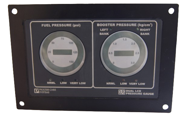
Dual LCD Pressure Gauge
This LCD pressure gauge panel will have analog inputs to measure pressures from a Fuel pressure transmitter and Booster pressure transmitter. The chosen microcontroller will have an ADC input, interrupting facility, general purpose I/O and capability to interface LCDs.
The panel will make use of two 31 segment circular bargraph LCDs to display fuel pressure and booster pressure. The pressure values will also be shown on the 7 segment LCD display for precise readings. There are six LEDs to indicate if any pressure is crossing the pre programmed limits.
The device will also provide for a regulated output voltage to power up pressure transmitters and thus protect sensors from spurious high voltages of Alternator.
GPS Based Speedometer
At times it may not be possible to have a speed sensor installed in certain vehicles. It is also possible that one doesn’t like using a speed sensor which is prone to wear and tear and is many times tricky to install. But knowing the speed of the vehicle is an important feature which can not be dispensed with. On such occasions GPS receiver can be deployed to determine the speed of the vehicle.
Our GPS Speedometer enables quick and accurate measurement of Vehicle Speed using GPS Receiver. The 85mm gauge is used to house the electronics required for GPS Speedometer. The microcontroller with a serial interface is used to read the GPS information in NMEA format. The received information is made use of to determine the speed in Km/H and put it on the LCD circular bar graph as well on the 7 segment display.
LED Tachometer
LED 7 segment displays are used to show the parameters like ENGINE SPEED
(rpm) and HOURMETER (h) at a glance. Here the parameters are
1. Hour meter – not resettable.
2. Tachometer – Real time indication of RPM.
1. Engine Speed (rpm) :
4 digit seven segment displays the real time value of rpm on the
first row. The resolution of RPM value is 1 rpm.
2. Hour meter (h):
6 digit seven segment display shows the hour-meter value on the second
row. The Value of Hour-meter increments for every 0.1 hour , i.e,.6 minutes.
Digital Voice Annunciation System
The Digital Voice Annunciation system which is installed at Level Crossing gates is used to alert the motorists and people around about an arriving train by announcing voice messages in Hindi, English and in a local language. This early announcement about arrival of train will avoid/reduce accidents at Level Crossing gates

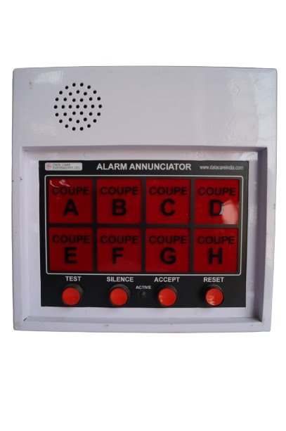
Annunciator System - EDTS117-Rev.'A'
The Annunciator System consists of housing, a micro-controller based annunciator unit, a buzzer and LED indicators for individual indication outside each coupe. The system consists of 8 LED back lighted windows corresponding to 8 different inputs from individual coupe in the coach. The LED back lighted windows displays the coupe number from which the call has been received. The Annunciator unit consists of four push buttons on the front panel namely ‘Test’, Silence, ‘Accept’ and ‘Reset’.
product is designed as per RCF specifications for LHB type coaches.
Specifications No :EDTS117-Rev.'A'
Engine Monitoring Device
ENGIMON 04 is a microcontroller based LED indicator system. On Power ON, the system simultaneously displays all four parameters namely water temperature, Lube oil temperature, Hydraulic pressure and Lube oil pressure. The height of the Display used is 0.5” and there are 3 digits for each parameter display. This system works on 24VDC supply. One of this display system is kept at Engine cabin and other slave display system is kept at Driver cabin. The slave system is connected to Master display system through CAT 5 cable
There are totally 5 relays used, 4 relays for ALARM and one relay for TRIP. One ALARM relay for each of parameter and TRIP relay is only for water temperature. Eight different sets of limits for each parameter can be set and this can be chosen by using DIP Switch. The temperature is sensed through RTD input and pressure is through loop powered transmitter.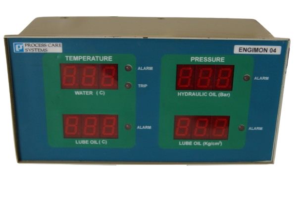
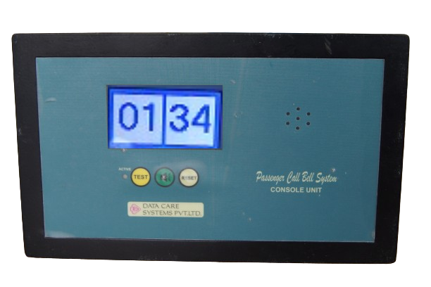
Passenger Call Bell System
The Passenger Call Bell System consists of one LCD based Operator Console Unit and 32 no.s Passenger Accessible Units (PAU). The front panel of the Console unit have one 128x64 pixel monochrome LCD, 2 membrane keys ‘Test’ and ‘Mute’ and one active LED. The top side of the unit have one wago connector to feed 110VDC power supply to the system and there are two RJ45 connectors (left and right) to connect Passenger Accessible Units. To left side of the RJ45 connector 16 Passenger Accessible Units which are on left side of the coach are connected in a cascading manner using CAT5 cables. Similarly to right side of the RJ45 connector 16 Passenger Accessible Units which are on right side of the coach are connected in a cascading manner. The system is powered by 110VDC power supply which is fed to only Console unit. All the Passenger Accessible Units will get power from the Console unit through CAT5 cables.
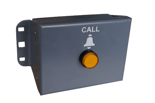
The Passenger Accessible Unit has one pushbutton with inbuilt LED on the front and two RJ45 connector on the rear panel. The pushbutton is used to generate and clear Call Request and RJ45 connectors are used to connect Passenger Accessible Unit with Console Unit/ other Passenger Accessible Units. Inside the unit, there is a Dipswitch through which unique address for Passenger Accessible Unit can be set. The 16 Passenger Accessible Units which are connected to left RJ45 connector of Console Unit. Similarly another 16 Passenger Accessible Units which are connected to right RJ45 connector of Console Unit.
The LCD display on the Console unit can display two alphanumeric names/symbols at time. The left half of LCD screen shows corresponding location/seat name when calls are initiated by 16 Passenger Accessible Units which are connected to left RJ45 connector of Console Unit. The right half of LCD screen shows corresponding location/seat name when calls are initiated by 16 Passenger Accessible Units which are connected to right RJ45 connector of Console Unit
Destination Display Boards
These are used in busses,trains, cabs and other vehicles.
- Luminosity of LEDs used allows for daylight viewing.
- Versatile and user friendly s/w for composing destinations in different languages.
- Available in Red and Amber color.
- User interface with full keypad.
- User interface module is designed to send destination information to a maximum of 16 display modules in a vehicle.
One can have destination shown on front, rear, side and inside the vehicle. - Provision for Pen Drive allows easy upgradation of station names.