welcome to
Production Line Monitoring System

Introduction
In a manufacturing industry, investment on the machinery is significant. Production operations by workers/machinery are carried out based on scientific management. At any cost production shouldn't be affected by lack of timely supply of components or breakdown of machinery or non availability of required tools. PROCESS CARE SYSTEMS has developed Production Line Monitoring System to communicate production parameters to a centralized system, to record those parameters and to use them for generating reports facilitating better management. In the Production Line Monitoring System (PLMS), machines are networked by connecting each machine to a MMU [Data Logger]. PC will receive the data from MMU and stores them.
Production Line Monitoring System is complete solution for maintaining the quality of product and effective utilization of machine time. It provides accurate and timely information on the real causes of downtime to enable increased output. It also frees supervisory personnel to do more value added work and production target information displayed on every MMU unit keeps operator busy.
Benefits of PLMS
Helps to maintain the quality of the manufactured product by recording the rejected quantity. The MMU Downtime Monitoring facility captures machine status in real time from production units. The information about machine down is made available to the operator through audio visual alarms.
Following are the benefits of the PLMS:
- Reduce the rejection of finished products.
- Increase the efficiency.
- Optimize uptime / Minimize Downtime.
Automation of data acquisition, reporting and analysis eliminates human errors and makes management information available instantly. Apart from these, stores details of about 8 different parameters like job code, operator code, down code, batch code, rejection code etc. Calculates current efficiency, production rates, Rejection rate, Utilization as well as OLE - Overall Line Effectiveness.
Functional Block Diagram
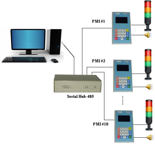
Production Line Monitoring System has several Modules viz: PC with enhanced application software, serial HUB-485, PMI(Production Monitoring Interface), Tower Lamp, Buzzer. The PMI is designed with serial communication port to interact with PC, tower lamp interface to indicate current status of the machine, buzzer interface to alert the operator if the machine is down, machine interface to read vital signals to derive production count and other status of machine, with display and keyboard interface for the operator to interact with the system. Three lamps with colors Red, Amber, Green in the Tower lamp are used to indicate different status of that particular machine/station. Machine running normally is indicated by lighting up of green lamp and down is indicated by continuous flashing of red lamp along with the buzzer.
Making use of in-built RTC, the PMI date and time stamps all the events and sends to the PC running PLMS application software. The software will maintain the database of all the events of all the machines, from which data base it will generate various reports and charts.
Main System Modules
Specifications
- LCD Display Window :128 x 64 pixels LCD
- Keypad : 20 keys
- Fn Keys : 6 nos.
- Numerals : 10 nos.
- Navigation : 4 nos.
- Communication Interface : RS485 on RJ45 jack
- Dimension (W x H x D) : 200mm x 112mm x 30mm
- Weight : 375gms
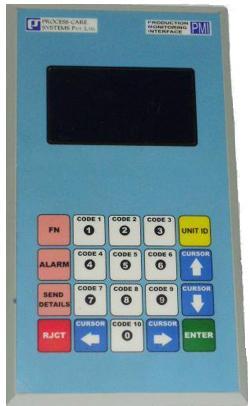
Production Monitoring Interface(PMI):
PMI(Production Monitoring Interface) is designed to read signals from process/production machine and send it to remote computer in addition to reflecting the same on the local display on Real time basis.
PMI contains:
- 128 X 64 pixels LCD module.
- Membrane keypad of 20 keys.
The PMI provides for 8 different parameters like job code, operator code, down code, batch code, rejection code etc. Each parameter will have 16 different entries. The keypad consisting of 20 membrane keys on the front panel will enable the user to select one of the entries of a parameter.
On power ON the machine status window will show “Idling”. After sensing “Start” pulse, i.e., while machine is running it will show real time. The cumulative count is incremented by one on sensing “Start” signal. The count will be decremented on pressing “Reject” key on the front panel. The cumulative count can be reset to zero either through keypad (with pass code protection) or through software.
If the next start pulse is not received within the down threshold time, the PMI will prompt the user to enter the reason code. If reason code is not entered within the interlock time then the machine will be disabled. On entering the reason code for which the machine is down, the machine will be enabled again. The enabling/disabling of the machine can be implemented using the potential free contact output of the PMI (e.g... wiring this potential free contact in series with the start push button).