Mining Equipments
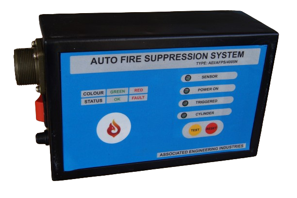
Auto Fire Suppression System (AFSS)
The Fire Suppression System consists of following components.
- Electronic Control Panel
- Sensor Cable
- N2 Cylinder
- DCP Cylinder
- Hoses
The system makes use of the sensor cable which has a pair of wires and will be run all around fire prone areas. In the event of this cable experiencing a temperature more than a certain value, this pair of wires gets short circuited which will be otherwise insulated from each other. It is this shorting that is sensed by the control panel to detect fire.
The system also makes use of two cylinders viz, DCP cylinder and N2 cylinder which are at different pressures and mounted with pressure switches for monitoring adequate pressure. The N2 Cylinder includes a squib which houses a heating element. The DCP cylinder contains dry chemical extinguishing agent.
The Electronic control panel continuously monitors the sensing wire, pressures in the cylinders and squib connectivity. If any of the above is not ok, the control panel will flash an alarm indication both visually and aurally.
If fire is sensed, the control panel detonates the squib and thus gets the dry chemical powder sprayed to extinguish the fire.
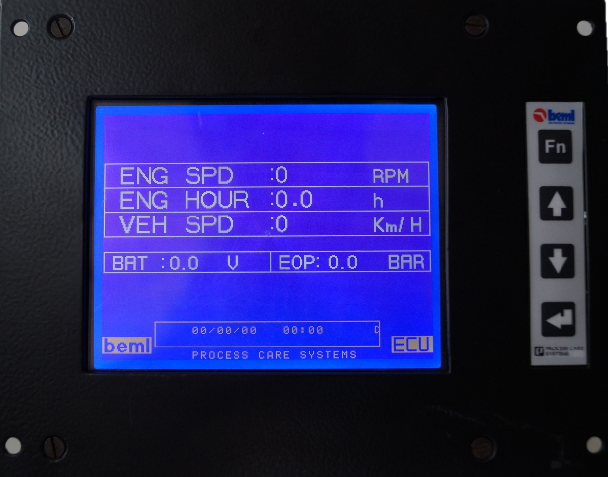
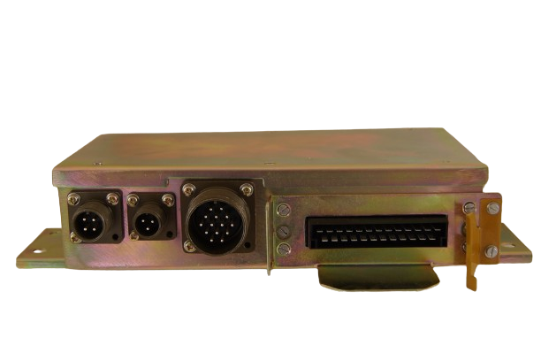
Electronic Control Unit for all terrain Heavy Duty Truck
This Electronic Control Unit (ECU) deployed on Heavy Duty Truck
performs the following functions:
- Cooling of Engine.
- Fuel control based on altitude at which the Truck is travelling.
- Turbocharger based Engine speed control.
- Engine Speed limiting.
- Preheating of Engine.
- Engine Brake Control.
- Monitor speed of the vehicle and distance travelled.
- Data acquisition, recording and retrieval.
- Real time parameter monitoring on an LCD display.
- Configuration of the system to suite different applications.
PayLoad Monitoring System
The Pay Load Monitoring System(PLMS) provides payload indication for the Dump trucks. It also provides overload warning to loading operator and records productivity data.
PLMS measures the weight of the load based on the principle of measuring the pressure in the hydro-pneumatic suspensions. The load is calculated by computing individual load on the suspension and adding them. The weight of the truck is subtracted digitally from the computed load to calculate net weight of the load. Payload measurement is done only when vehicle is standstill to avoid erroneous load computation during travel.
In addition to the above, system provides LED indication on the PLMS unit and deck
lamps outside the cabin to display loading status. On occurrence of overload, system will
warn both the dumper and shovel operator through deck lamp and buzzer.
PLMS facilitates easy operation of the unit with the help of 16/2 ASCII Display LCD module and 4
keys keypad. It supports the following operations,
- System set up
- System Initialization
- Load Calibration and Taring
- Printing/viewing recorded data
- Diagnostics

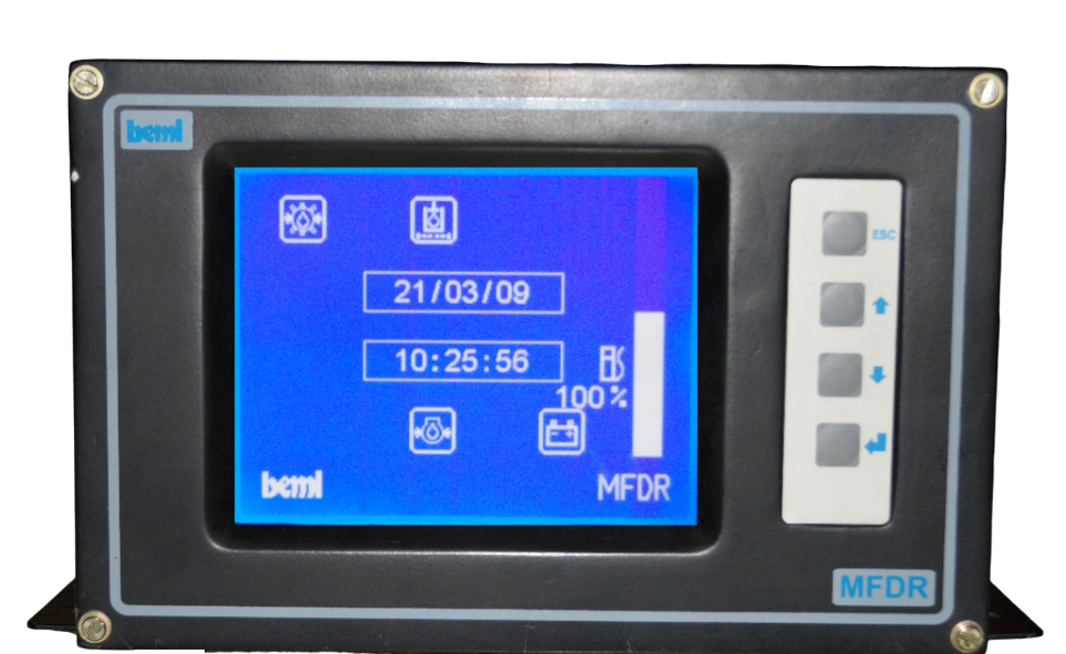
Multi Function Data Recording Systems
An LCD based Data Acquisition system for real time scanning of critical vehicle parameters for the purpose of data logging, audio visual warning and to assist vehicle maintenance scheduling.
The system accepts ON/OFF and analog signals from electromechanical switches and sensors fitted on the equipment subsystems. It will log real time data to provide enhanced diagnostic message. The logged data can be retrieved later to study equipment history failure analysis.
Key Switches :There are 4 key switches namely ESC, INC, DEC and ENTER to operate certain basic functions like display of equipment parameter, set limits ,modify calibration table etc.
Engine shut off :The engine will shut off automatically , when some of the specified parameters crosses the set limit.
Display :The unit consists of 320x240 pixels graphic programmable LCD display with provision to change the intensity of the screen. This LCD display is used to display the various warning messages, operating hours of the vehicle, vehicle speed in digital format and for pilot indication.
Audio Visual Warning :
- When parameter reaches the warning point , the symbol of the corresponding parameter flashes and buzzer will become on.
- In case of Engine shutoff , the engine stop symbol flashes and buzzer will be on.
- Service alarm for all temperatures, pressure and filter clog.
- In case of failure of sensor, filter clog ,cable break ,low fuel level.
Data storage :The vehicle parameters are recorded for a duration of 24 hours The sampling rate of vehicle parameters during normal and faulty conditions is varying between 0.5 sec to 5 minutes. The stored data can be retrieved in the form of graphical representation. The sampling rate is changed automatically from maximum to minimum during faulty conditions. The unit will have battery back up memory to hold the recorded data in the absence of equipment battery.
Printer interface :The unit will have provision for downloading the recorded data through serial RS232 port to an external devices (PC or Printer) for further analysis. There will be provision in the system to share and accept vehicle information from other vehicle electronic modules.
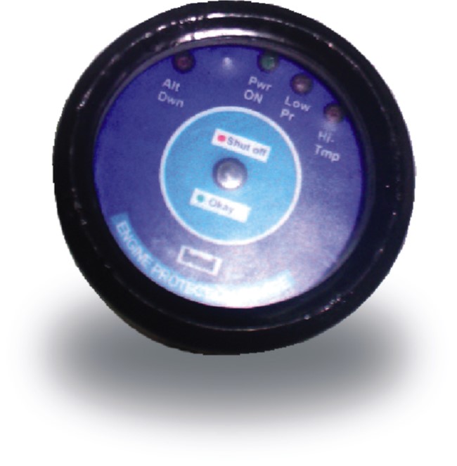
Engine Protection Device
Designed to monitor engine parameter faults like Temperature, Pressure and Engine RPM so that engine shut off signal can be given after validating faults. It also indicates for what reason the engine is shut off.
GPS Based Speedometer
At times it may not be possible to have a speed sensor installed in certain vehicles. It is also possible that one doesn’t like using a speed sensor which is prone to wear and tear and is many times tricky to install. But knowing the speed of the vehicle is an important feature which can not be dispensed with. On such occasions GPS receiver can be deployed to determine the speed of the vehicle.
Our GPS Speedometer enables quick and accurate measurement of Vehicle Speed using GPS Receiver. The 85mm gauge is used to house the electronics required for GPS Speedometer. The microcontroller with a serial interface is used to read the GPS information in NMEA format. The received information is made use of to determine the speed in Km/H and put it on the LCD circular bar graph as well on the 7 segment display.
